rig placement
Tools & Techart Topics
It's been a while since I posted something on my website and while digging through my rnd folder I found this setup again and realized I might as well put it out there as it might be useful to others.
The idea behind this setup is not only that the rig can be modified after skinning, but its also a way to make a (modular) automated rig setup without the need for scripting. This makes use of a placer rig, which are just simple controls that provide the position for the controls and the joints of the final rig. Once the controls are in place, the rig itself can take over the control of the mesh, the user would be able to delete the placement controls or just lock them away so the animator cannot break the setup. And because we can pipe the prebindmatrix information to the skincluster we have a way to modify the joint placement for a better outcome in the skinning before we finalize the setup. the only caveat to this is that breaking the connection from the inverseMatrix to the prebindMatrix on the skincluster does not store the information so this will require some scripting in order to make it work properly.
The setup takes some of the basic joint placing principles and uses vector math nodes to create matrices that drive the skeleton and rig:
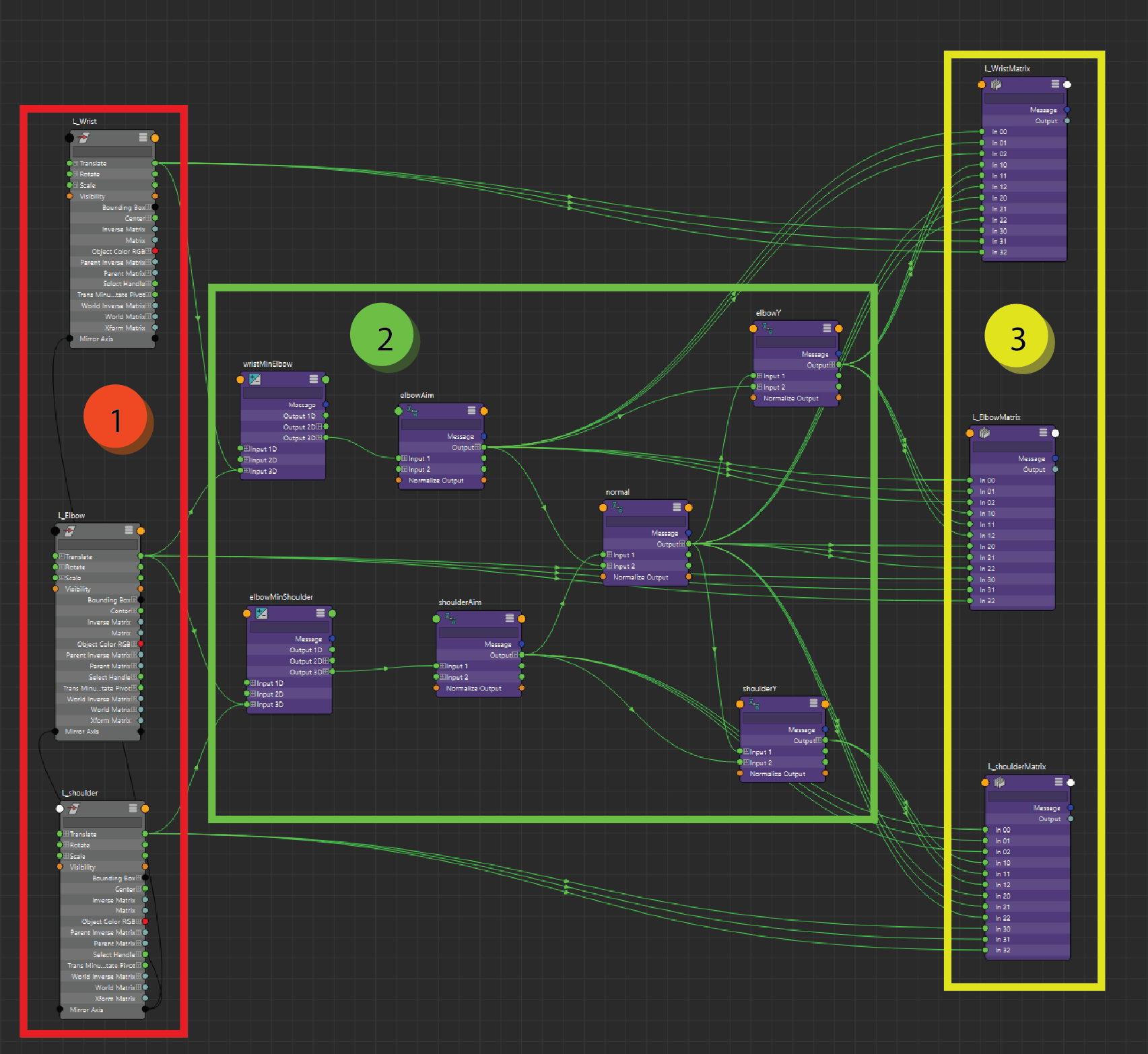
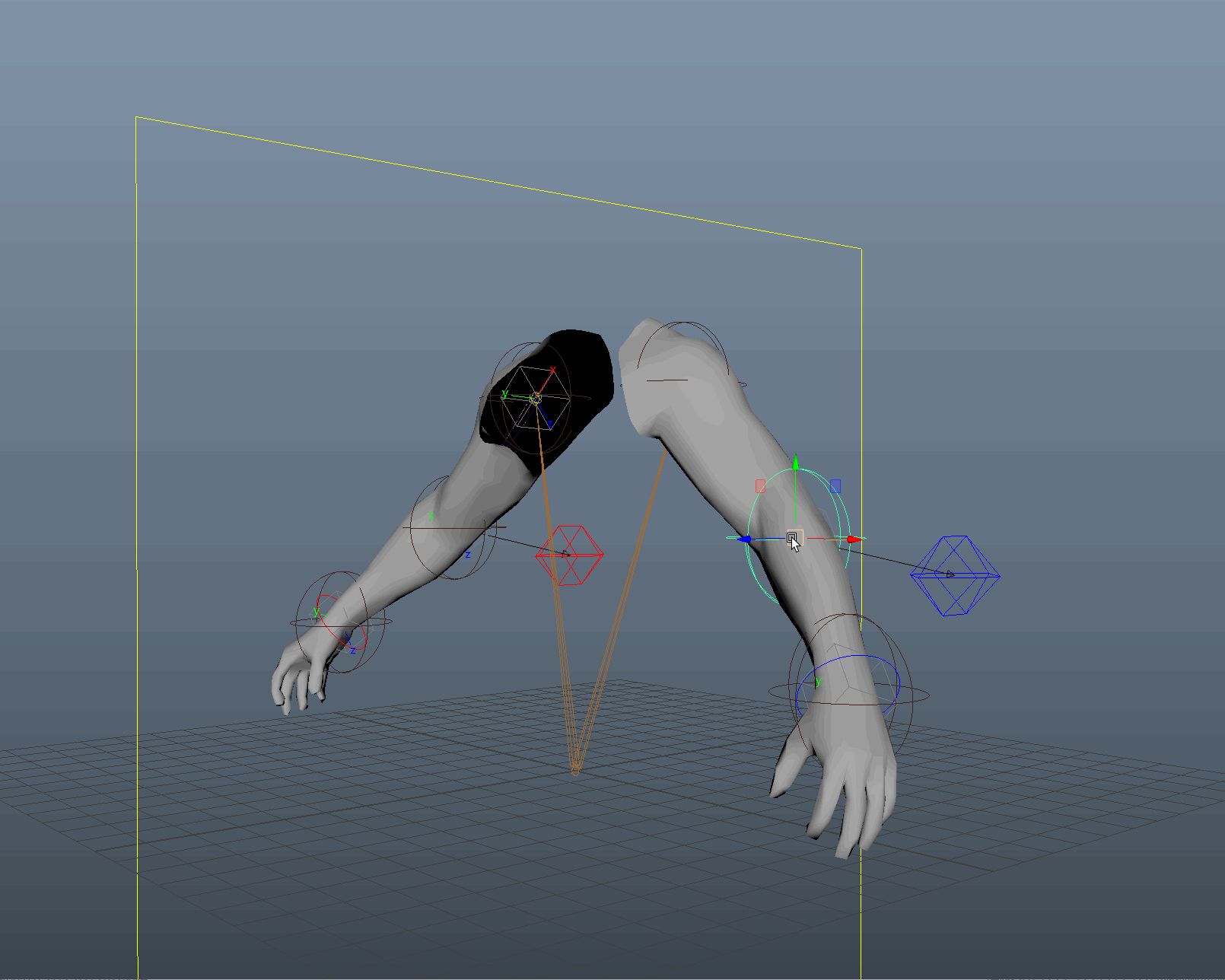
to simplify the explenation I will only talk about the left side of the rig as the right side is almost the same (the last image will show how the mirrored setup for the right side controls is created). The arm consists out of 3 placement controls (1), we can place these controls wherever we need them in the scene and the position will drive the placement setup. In order to make this work in any type of environment you could decompose the worldmatrix and grab the position from there, but in thise case the position of the controls works well enough. 3 positions in space can create a plane and a normal (2), we use basic vector math to find out which vector points to the next placer in line. once we have the shoulder and elbow aim we can use this to derive the normal by using a cross product. (this setup does not take into account if the placers are exactly alligned, it needs to have at least a slight difference in its position to create the triangle/plane as mentioned before) now that we have a pointAt and a normal for the shoulder and the elbow we can use this to create the rotation matrix but using a cross product of these elements, the 3 vectors together can be used to create the matrix (3), the wrist will take the same orientation as the elbow and takes the position of the wrist placer. position for the shoulder is derived from the matrix itself while the position on the elbow and wrist is a direct connection of the distance between the placers to the translateX of the joints and controls.
now we converted 3 positions in space to 3 matrices with the correct position and orientation for the joints and controls. These positions are all in worldspace, while our controls and joints are all in a local space. from here we could cheat our way and turn off the inheritsTransform attribute which will ignore all parentspace calculations on the driven object, but since I work mainly with rigs for games that luxury tends to give more problems then it solves when you export the rig.
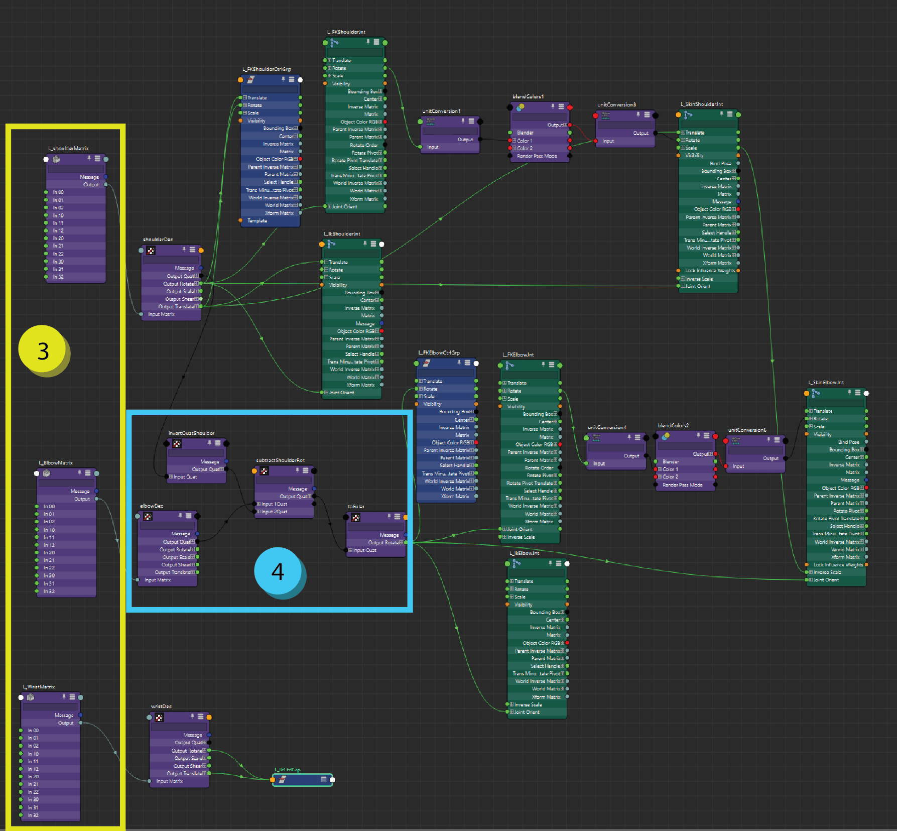
we take the worldMatrix information (3) from our previous calculations and we decompose them back to values we can easily work with (translate, rotate, scale). for the shoulder since the arm is not connected I opted for a direct connection from the translate and rotate of our decomposed setup. if the shoulder needs to be connected to something else the graph will need a multmatrix node in order to calculate the local space as well, in maya the setup for this is: child worldMatrix * parent's worldMatrix inversed = child localMatrix. in this case I only need to fix the joint orient of the elbow (4). its basically the same as the math in matrices above but in order to only work with the necessary elements I opted for the approach which uses quaternions. it uses the quaternionProd to combine the child worldspace quaternion with the inverse quaternion of the parent to get the local quaternion. we convert this back to euler space and connect that directly to the joint orient The wrist does not need to be fixed as its taking 0 rotations in rotate and in the joint orient, so that's easy enough.
all the other connections from here are just to make the rig work as intended, the placers control the information on the offsets for each control as well so the controls themselves should be clean in any position. from here we can have a look at how the skincluster is driven.
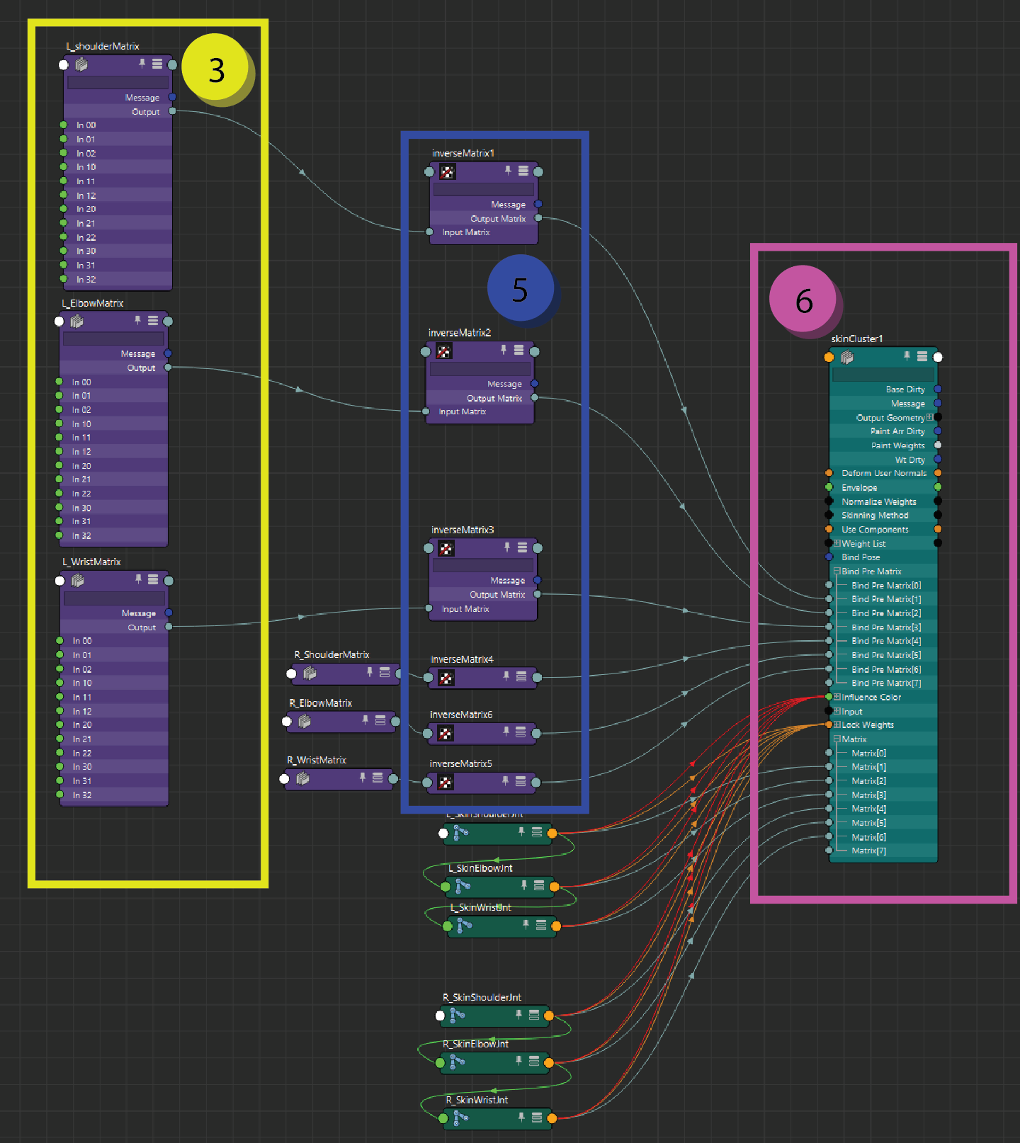
the skincluster uses the worldspace matrix information of the bones to deform a mesh, in the same way that a skincluster needs a original mesh (origShape) to identify the original positions of each vertex to know how these are moved by outside influences the joints need an original position as well. this information can be found on the skinclusters bindPreMatrix attribute (6). this attribute is an array of matrices that is set on the skincluster when the mesh is bound. the index of the prebind matrix corresponds to the index of the joint in the matrix attribute, so be carefull when you connect the objects together. the setup we originally start with (3) actually has worldspace information and since the prebindmatrix uses the worldInverseMatrix, the only thing we have to do is invert the information (5) before we pipe it into the skincluster. as mentioned before, this will allow the skeleton to be modified wihtout deforming the skincluster, but if the connection is broken it will jump back to the default infromation as the matrix info is not stored. in order to make this work the inverse matrix needs to be set by code onto the skincluster.
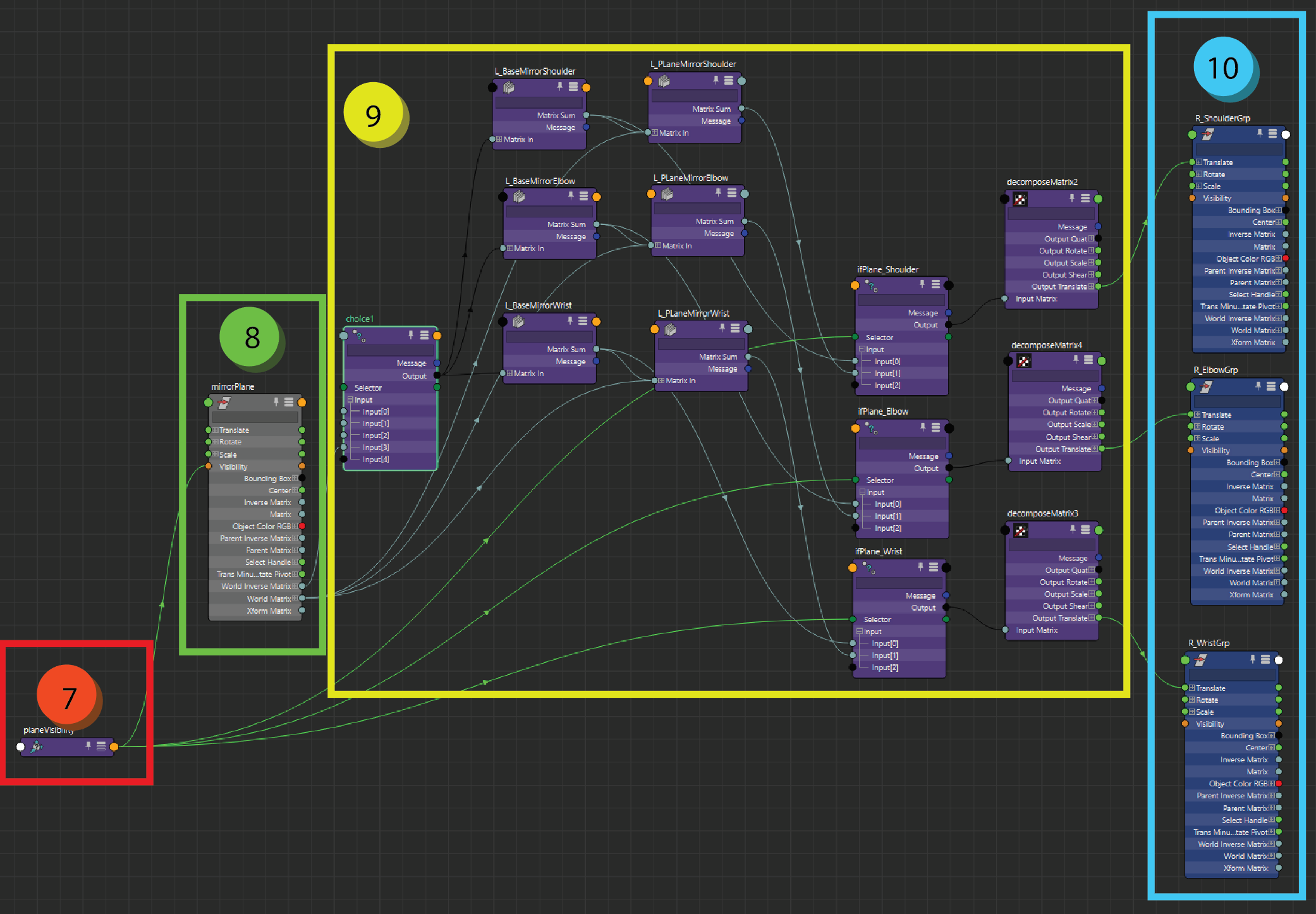
and as a little extra there is a mirror setup embedded in the rig. this helps speed up the postitioning of the placers as the right side is automatically matched with the left side, with the posibility to move the right side for when the character is asymetrical. the setup currently uses a nurbsPlane (8) from which the matrix is multiplied (9) in order to place the offset groups (10) on the mirrored position. the choice node (7) is there to make sure that the user is able to select the correct mirror axis. the first 3 options are default worldspace mirror setups and the last takes the plane information.
if you want to have a deeper look into this setup, the file can be found here: Maya 2019 file