single node IkFk R&D
Tools & Techart Topics
Back in 2010 my friend Jan Pijpers and I went on a quest as eager students to figure out if we could remove the ik/fk blend system and make it a single element. the test was hacky and valid but showed us that it opened up a whole lot of extra problems. the setup was not usable or even something that could replace the standard methods, but the knowledge gained was great.
Now 16 years later I opened up that idea again. Not to replace the existing systems, but in search for new knowledge.
The question for this test is:
Can a Maya arm component behave mostly like one rig-control object, while the pose data, viewport display, manipulators, and output matrices live inside a plugin shape?
This post is a breakdown of what has been tested so far.
basic rules
The rules were:
- everything should live inside one .mll plugin
- preferably one visible component object
- Python setup code is fine for testing, but the final behavior should move into the plugin or be discarded
- focus on interaction and UX
The goal was not to build a finished rig. The goal was to find out where the idea breaks.
blockout
first off the node blockout, what sort of attribute data are we looking at
the idea is a simple 3 bone setup that makes up the arm, we would need a base pose to start from and elements that we need to expose as outputs;
- shoulder
- elbow
- wrist
if we make these matrices then we can plug the world matrix data of locators or joints and have those be our base at the same time we could use the inversematrix to plug the bindPreMatrix data on a skincluster to make sure we can repose the controls without breaking the skinning something similar as done here
next up the bevaviour we want to embed in the plugin from the start:
- use the pose data for placement of controls
- define polevector from the arm data
- draw debug elements
- drive ik with fk and vice versa
- manipulators
since we are dealing with a single plugin setup we will have to make smaller chunks of tests before we can know for sure if everything works out these single test elements will be the main takeway and learning path we want to achieve.
so we can start from this point and setup our learning path: part 1 - Defining the component part 2 - Proving the pose setup part 3 - Replacing Maya Builtin manipulators part 4 - mesh based controls part 5 - ik and polevector integration part 6 - shoulder and elbow fk integration part 7 - re-evaluate
once we reach part 7 we have enough data to look into how we distribute the manipulation of the controls since fk and ik have a distinct behaviour patern we will need to look at how we want to expose these. we can use the handles, manipulators and general node for posing and manipulating the arm, while we expose an attribute that will handle the blending from pose to pose, where we use linear motions for ik and spherical motions for fk.
the basic setup
In Maya, a shape still lives under a transform. So this is not just one node.
so we describe the prototype like this:
parent transform non-keyable DAG container
plugin shape owns pose attributes owns rest matrices owns output matrices owns control display data owns active handle state
custom manipulator layer draws the controls handles picking handles dragging writes pose attributes
compute reads rest matrices and pose attributes outputs matrices does not write pose attributes
This became the most important rule in the project: compute should not fix or sync pose data.
All pose changes should happen through explicit C++ edit operations. compute should only read the current stat and output matrices.
every time compute was used for direct manipulation it locked the node or created cycles.
part 1 Defining the component
The first step was blocking out the data.
The arm needs three rest matrices:
restShoulderMatrix restElbowMatrix restWristMatrix
These define the setup pose of the arm. They can come from joints or locators during setup.
The animator-facing pose data lives on the plugin shape:
poseShoulderTranslate / Rotate / Scale poseElbowTranslate / Rotate / Scale poseWristTranslate / Rotate / Scale posePoleTranslate
The pole only needs translate values for now. The shoulder, elbow, and wrist use translate, rotate, and scale.
I could have stored this as matrices, but that would be bad for animation. Float attributes are easier to key, easier to inspect, and they create readable animation curves.
The outputs are matrices:
outShoulderMatrix outElbowMatrix outWristMatrix
For testing, these can be connected to locator offsetParentMatrix attributes. Later they could be tested with joints or direct plug to a skincluster.
One important decision was that the parent transform should not be animated. If Maya puts keys on the parent transform, the component state gets split between the transform and the shape. That is exactly what I wanted to avoid. Pressing S should key the pose attributes on the plugin shape, not random transform channels on the parent.
So the parent transform became just a container. The plugin shape owns the actual animation data.
part 2 Proving the pose setup
The first real test was this:
rest matrices + local pose attributes = output matrices
The pose attributes are local values based on the rest matrices. This keeps the animator channels clean, while the plugin can still produce world-space output matrices.
In this phase I needed to prove:
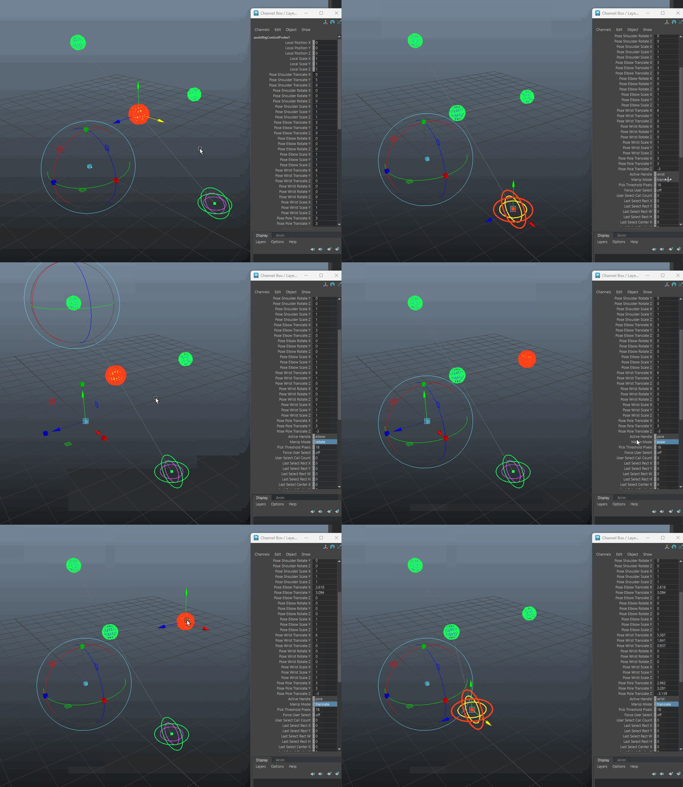
pose attributes could be keyed the parent transform could stay non-keyable rest matrices could drive the setup output matrices updated correctly active handle state worked manipulator mode state worked
The first version used Maya’s built-in manipulators. That was useful at the start because it proved that the plugin shape data could be edited and evaluated.
But it also showed the next problem.
Built-in manipulators were not strict enough for this component. The component needed different behavior per handle. The shoulder should not translate. The pole should not rotate or scale. The wrist should support translate, rotate, and scale.
That pushed the project toward custom manipulators.
part 3 Replacing Maya Builtin manipulators
The handle rules are:
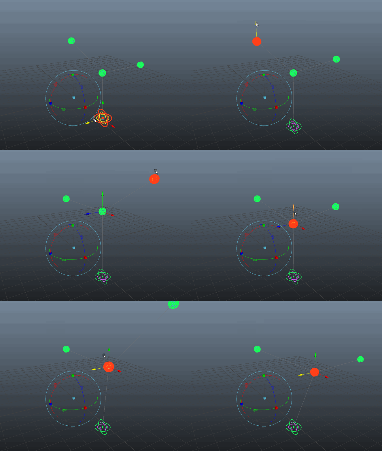
shoulder = rotate + scale elbow = rotate + scale wrist = translate + rotate + scale pole = translate
This sounds simple, but it matters a lot.
If the pole vector is selected, rotate and scale should not be visible. If the shoulder is selected, translate should not be available. The manipulator should only show what the selected handle can actually do.
The Maya built-in manipulators did not give me enough control over that. Some parts would remain visible or available even when they made no sense for the selected handle.
So I removed the built-in manipulators and started drawing the manipulation controls myself.
The custom manipulator needed:
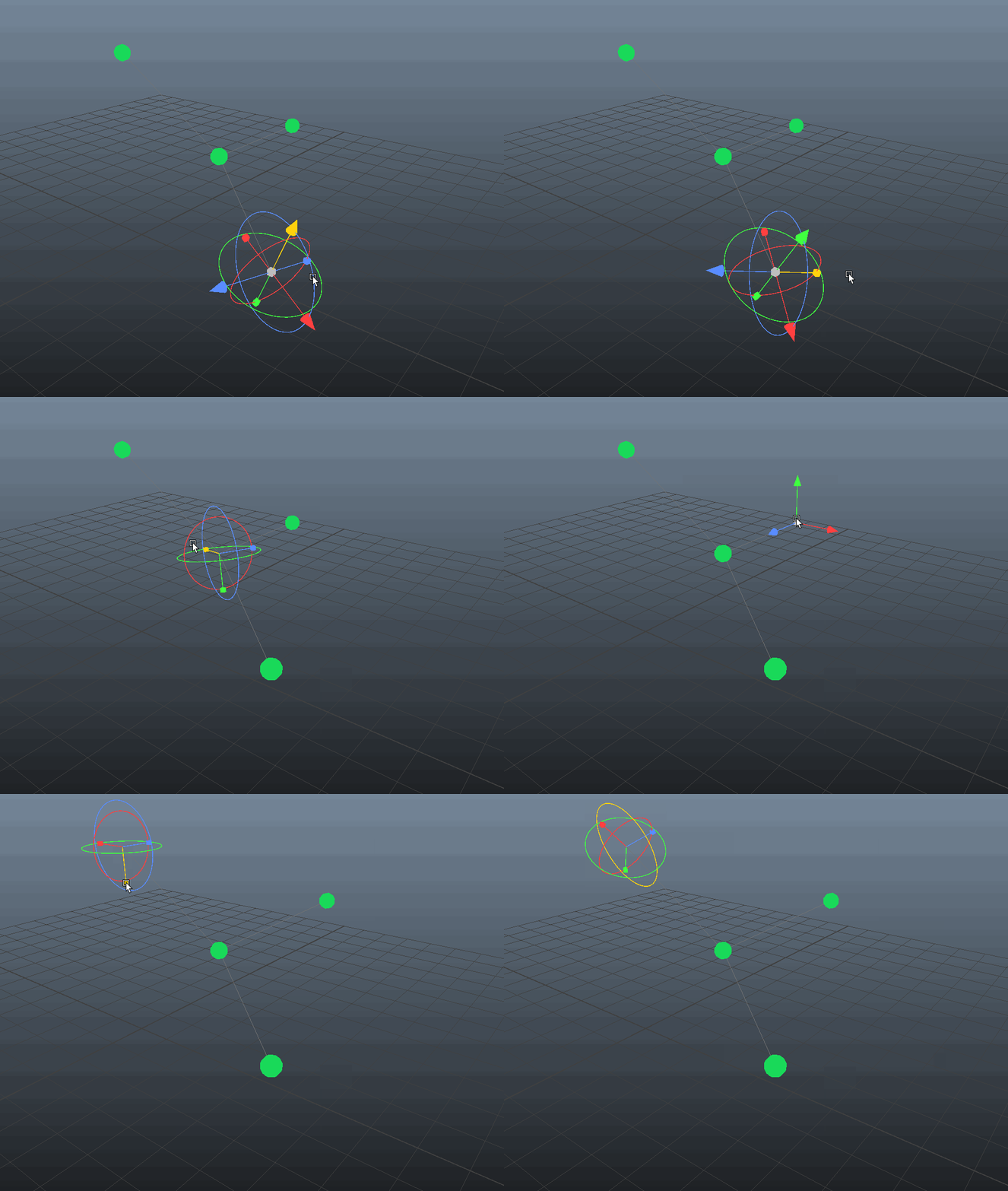
handle markers = filled spheres translate axes = filled cone arrows translate center = filled cube with view-plane movement rotate controls = local/object rings scale controls = filled cubes active state = color highlight rotate feedback = angle arc
This was one of the bigger validation points of the project.
The plugin now had to draw, pick, drag, and write the pose attributes itself.
The most important UX rule was this:
If the arrow points in a direction, dragging it must move in that direction.
The visible gizmo has to be the truth. If the visual direction and the actual edit direction do not match, the manipulator cannot be trusted.
Rotation was the hardest part. I first tried a more Euler-based setup that showed the rotation axes parented together. It was interesting to show gimbal lock, but not at all animator friendly. In the end I used local rotation rings visually, then applied quaternion based rotation deltas and converted them back to Euler values for the attributes.
That gave me a custom manipulator path that was good enough to continue.
MStatus RigControlMarkerManip::doPress(M3dView& view)
{
    resetCustomDrag();

    if (fNode.isNull())
    {
        return MS::kUnknownParameter;
    }

    updateCachedPoints();

    MGLuint activeName = 0;
    MStatus status = glActiveName(activeName);
    CHECK_MSTATUS_AND_RETURN_IT(status);

    if (activeName == 0)
    {
        return MS::kUnknownParameter;
    }

    if (activeName == fShoulderHandleName)
    {
        return pressMarkerHandle(kMarkerHandleShoulder, fShoulderPoint);
    }

    if (activeName == fElbowHandleName)
    {
        return pressMarkerHandle(kMarkerHandleElbow, fElbowPoint);
    }

    if (activeName == fWristHandleName)
    {
        return pressMarkerHandle(kMarkerHandleWrist, fWristPoint);
    }

    if (activeName == fPoleHandleName)
    {
        return pressMarkerHandle(kMarkerHandlePole, fPolePoint);
    }

    const short customComponent = customComponentFromSelectionName(activeName);
    if (customComponent != kCustomManipComponentNone)
    {
        return pressCustomManipulatorComponent(customComponent, view);
    }

    return MS::kUnknownParameter;
}
This is the point where the component stops depending on Mayas default manipulator behavior.
The drawn handle or manipulator part becomes the selected thing. From there the plugin can decide exactly what kind of edit is allowed for that handle.
part 4 mesh based controls
The first control display used simple spheres and rings. That is fine for testing, but not enough for actual authored controls.
In a normal rig, animators usually interact with NURBS control shapes. For this prototype, I wanted to test if the plugin shape could store its own control display data instead.
The test was:
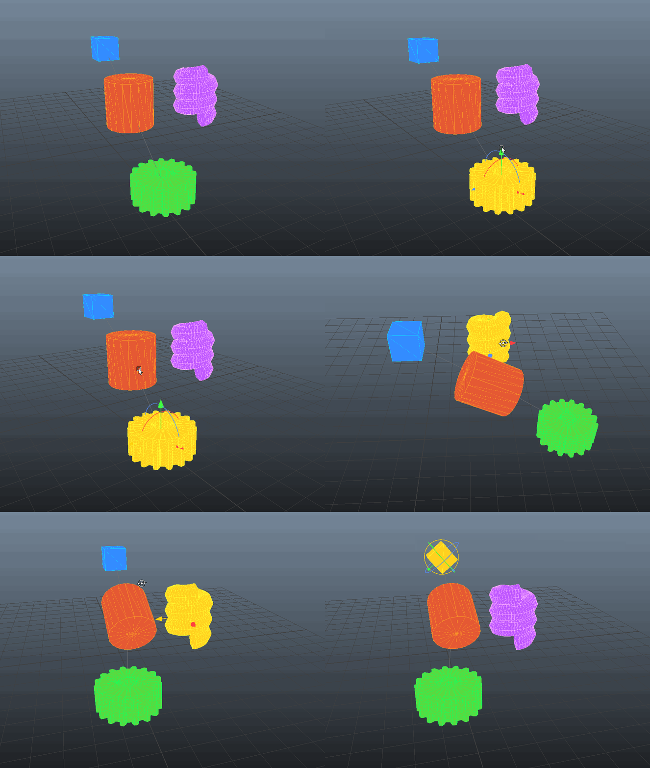
take a mesh object from the scene store its shape data on the plugin shape draw that stored data in the viewport remove the need for the original mesh object
For each control mesh, the plugin stores:
vertex positions triangle indices
That is all I needed for this test. I did not store normals, UVs, materials, or anything extra. The mesh is drawn double-sided, so the data can stay small.
This is only display data.
The mesh control does not solve the arm. It does not replace the manipulator. It gives the component an authored control shape, while the custom manipulator still owns the actual picking, dragging, and writing.
with some hassle i managed to set this up, the mesh is drawn using the MPxDrawoverride, we dont use MPxGeometry oveverride for these as it would change the entire architecture of the plugin.
MFnMesh mesh(meshPath, &status);
CHECK_MSTATUS_AND_RETURN_IT(status);

MPointArray sourceWorldPoints;
status = mesh.getPoints(sourceWorldPoints, MSpace::kWorld);
CHECK_MSTATUS_AND_RETURN_IT(status);

MIntArray triangleCounts;
status = mesh.getTriangles(triangleCounts, fNewTriangleIndices);
CHECK_MSTATUS_AND_RETURN_IT(status);

const MMatrix probeWorldInverse = probePath.inclusiveMatrixInverse(&status);
CHECK_MSTATUS_AND_RETURN_IT(status);

const MMatrix localHandleInverse = handleMatrix(probeNode, handle).inverse();

fNewPoints.setLength(sourceWorldPoints.length());

for (unsigned int i = 0; i < sourceWorldPoints.length(); ++i)
{
    const MPoint probeLocalPoint = sourceWorldPoints[i] * probeWorldInverse;
    fNewPoints.set(probeLocalPoint * localHandleInverse, i);
}
The source mesh is converted into local data for the handle. After that, the original mesh does not need to stay in the scene.
For this test I only store points and triangle indices. That keeps the control display simple and makes it easier to prove that the plugin owns the display data.
part 5 ik and polevector integration
Once the control display and custom manipulator path worked, the next step was actual arm behavior.
The first target was minimal two-bone IK.
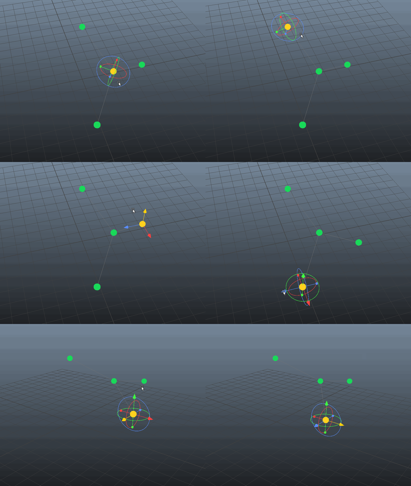
The wrist translate handle and pole translate handle trigger the IK solve. The result is written back into the pose attributes on the plugin shape.
That part is important.
There is no separate IK chain in the scene. The IK edit writes back into the same pose state used by the rest of the component.
The flow is:
wrist or pole drag -> C++ IK solve -> write pose attributes -> compute output matrices
MStatus RigControlMarkerManip::solveAndWriteIkTranslateVector(const MVector& value)
{
    const PoseSnapshot currentPose = readPose();

    TwoBoneIkInput input;
    input.restShoulderMatrix = readMatrixPlug(fNode, PersonalRigControlProbeNode::aRestShoulderMatrix);
    input.restElbowMatrix = readMatrixPlug(fNode, PersonalRigControlProbeNode::aRestElbowMatrix);
    input.restWristMatrix = readMatrixPlug(fNode, PersonalRigControlProbeNode::aRestWristMatrix);

    input.currentShoulderTranslate = currentPose.shoulderTranslate;
    input.currentShoulderRotate = currentPose.shoulderRotate;
    input.currentShoulderScale = currentPose.shoulderScale;

    input.currentElbowTranslate = currentPose.elbowTranslate;
    input.currentElbowRotate = currentPose.elbowRotate;
    input.currentElbowScale = currentPose.elbowScale;

    input.currentWristTranslate = currentPose.wristTranslate;
    input.currentWristRotate = currentPose.wristRotate;
    input.currentWristScale = currentPose.wristScale;

    input.currentPoleTranslate = currentPose.poleTranslate;

    if (fDragHandle == kHandleWrist)
    {
        input.wristTarget = MPoint(value.x, value.y, value.z);
        input.poleTarget = MPoint(
            currentPose.poleTranslate.x,
            currentPose.poleTranslate.y,
            currentPose.poleTranslate.z
        );
    }
    else
    {
        input.wristTarget = pointForActiveHandle(kHandleWrist);
        input.poleTarget = MPoint(value.x, value.y, value.z);
    }

    TwoBoneIkPose solvedPose;
    if (!solveTwoBoneIk(input, solvedPose))
    {
        return MS::kFailure;
    }

    PoseSnapshot nextPose;
    nextPose.shoulderTranslate = solvedPose.shoulderTranslate;
    nextPose.shoulderRotate = solvedPose.shoulderRotate;
    nextPose.shoulderScale = solvedPose.shoulderScale;
    nextPose.elbowTranslate = solvedPose.elbowTranslate;
    nextPose.elbowRotate = solvedPose.elbowRotate;
    nextPose.elbowScale = solvedPose.elbowScale;
    nextPose.wristTranslate = solvedPose.wristTranslate;
    nextPose.wristRotate = solvedPose.wristRotate;
    nextPose.wristScale = solvedPose.wristScale;
    nextPose.poleTranslate = solvedPose.poleTranslate;

    return writePoseDirect(nextPose);
}
The useful part here is not the IK math. The useful part is where the result goes.
The manipulator does not create a separate IK chain. It reads the current pose, solves the new arm position, then writes the full pose back to the plugin shape.
The first version only updated translations. After that, the solve path was expanded to update rotations as well.
At this point the prototype proved that the custom manipulator could drive a two-bone IK solve and write the result back into the plugin shape.
part 6 shoulder and elbow fk integration
After IK worked, the harder part was shoulder and elbow manipulation.
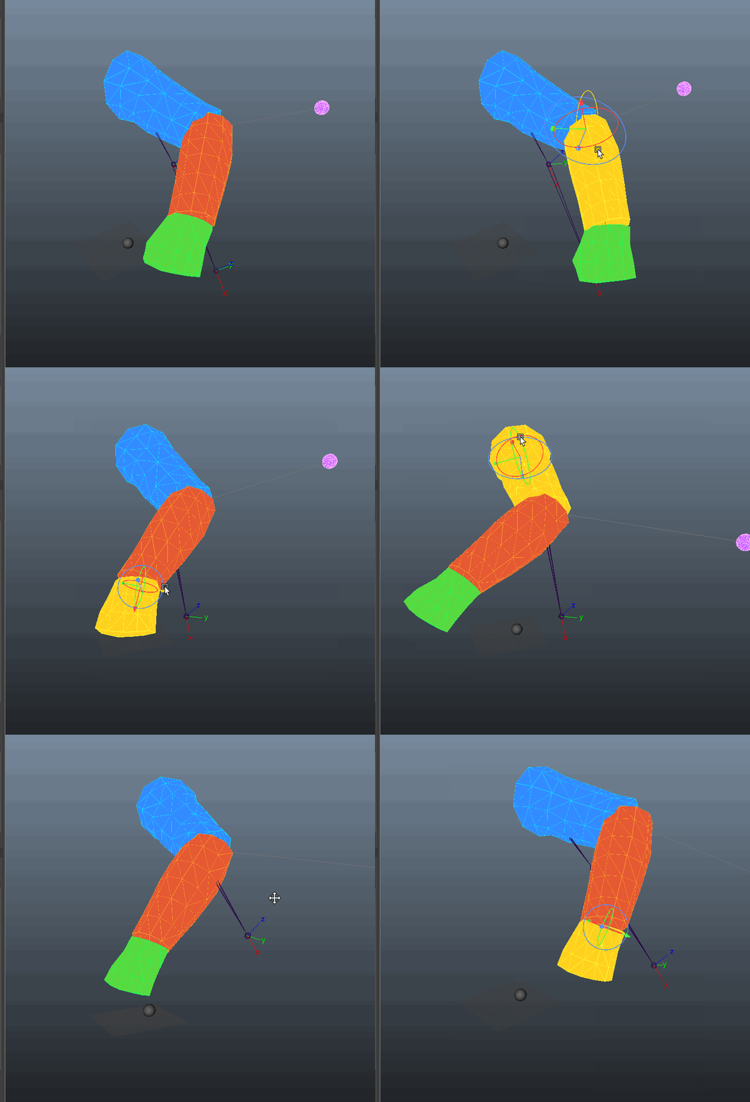
The shoulder and elbow behave more like FK controls. Moving them should pose the arm directly, but the full component still needs to stay in a valid state. The wrist and pole positions also need to stay meaningful after those edits.
This is where an earlier mistake became clear.
At first, too much logic was inside compute. That worked while testing isolated IK behavior, but it became a problem once FK-style shoulder and elbow were added.
compute was starting to do more than evaluate the result. It was becoming part of the pose editing logic.
That was the wrong place for it.
The fix was to move the pose syncing into the manipulator edit path.
MStatus RigControlNode::compute(const MPlug& plug, MDataBlock& dataBlock)
{
    if (plug == aOutShoulderMatrix)
    {
        return computeOutputMatrix(
            dataBlock,
            aRestShoulderMatrix,
            aPoseShoulderTranslate,
            aPoseShoulderRotate,
            aPoseShoulderScale,
            aOutShoulderMatrix
        );
    }

    if (plug == aOutElbowMatrix)
    {
        return computeOutputMatrix(
            dataBlock,
            aRestElbowMatrix,
            aPoseElbowTranslate,
            aPoseElbowRotate,
            aPoseElbowScale,
            aOutElbowMatrix
        );
    }

    if (plug == aOutWristMatrix)
    {
        return computeOutputMatrix(
            dataBlock,
            aRestWristMatrix,
            aPoseWristTranslate,
            aPoseWristRotate,
            aPoseWristScale,
            aOutWristMatrix
        );
    }

    return MS::kUnknownParameter;
}
The new flow became:
shoulder or elbow drag -> C++ edit operation -> update pose attributes -> update pole position -> compute output matrices
This is intentionally boring. That is the point.
The compute function does not decide what the pose should be. It only takes the current rest matrix and pose attributes for the requested output, then builds the output matrix.
No IK matching. No FK syncing. No pole-vector repair. No hidden pose edits.
Those edits happen before compute runs.
MStatus PersonalRigControlProbeMarkerManip::writePoseDirect(
    const PoseSnapshot& pose
) const
{
    if (fNode.isNull())
    {
        return MS::kFailure;
    }

    MStatus status = setCompoundVectorValue(
        fNode,
        PersonalRigControlProbeNode::aPoseShoulderTranslate,
        pose.shoulderTranslate
    );
    CHECK_MSTATUS_AND_RETURN_IT(status);

    status = setCompoundVectorValue(
        fNode,
        PersonalRigControlProbeNode::aPoseShoulderRotate,
        pose.shoulderRotate
    );
    CHECK_MSTATUS_AND_RETURN_IT(status);

    status = setCompoundVectorValue(
        fNode,
        PersonalRigControlProbeNode::aPoseElbowTranslate,
        pose.elbowTranslate
    );
    CHECK_MSTATUS_AND_RETURN_IT(status);

    status = setCompoundVectorValue(
        fNode,
        PersonalRigControlProbeNode::aPoseElbowRotate,
        pose.elbowRotate
    );
    CHECK_MSTATUS_AND_RETURN_IT(status);

    status = setCompoundVectorValue(
        fNode,
        PersonalRigControlProbeNode::aPoseWristTranslate,
        pose.wristTranslate
    );
    CHECK_MSTATUS_AND_RETURN_IT(status);

    status = setCompoundVectorValue(
        fNode,
        PersonalRigControlProbeNode::aPoseWristRotate,
        pose.wristRotate
    );
    CHECK_MSTATUS_AND_RETURN_IT(status);

    status = setCompoundVectorValue(
        fNode,
        PersonalRigControlProbeNode::aPosePoleTranslate,
        pose.poleTranslate
    );
    CHECK_MSTATUS_AND_RETURN_IT(status);

    return MS::kSuccess;
}
scale values are omitted from the snippet above for readability
The result is that IK-style wrist and pole edits, and FK-style shoulder and elbow edits, can both write into the same pose data without using separate IK and FK scene chains.
part 7 re-evaluate
now most of the setup is proven and confirmed I am taking a break from the project to clean up the code for future reference and rethink the necessary steps. so far the current plugin consists of:
DAG-visible plugin shape owns pose data owns rest data owns output matrices owns embedded control display
non-keyable parent transform exists only as DAG container
custom manipulator draws and picks handle-specific controls writes through C++ edit operations
C++ write policy layer (manipulator setup) owns pose synchronization handles FK-style and IK-style manipulator writes
compute remains clean reads rest + pose attrs outputs matrices
What has been proven
So far, the prototype proves that:
- the plugin shape can own the pose data
the parent transform can stay as a non-keyable container
- the component can draw its own viewport controls
- Mayas builtin manipulators can be replaced
- each handle can expose only the manipulation modes it supports
- mesh control shapes can be stored on the plugin shape
- wrist and pole edits can drive a two-bone IK solve
- shoulder and elbow edits can pose the chain in an FK-style way
- both IK-style and FK-style edits can write into the same pose data
- compute can stay clean and only output matrices
The biggest lesson so far is this:
edit operations change pose data compute reads pose data and outputs matrices
Keeping that line clear is what made the prototype stable enough to continue.
What is not solved yet / whats next
The next problems are:
- test the selection priority of embedded mesh controls and manipulators
- manipulator orientation in rest space
- initialize the pole vector cleanly from the rest matrices
- make manipulator size match the authored control shapes or full chain
- improve bounding boxes for embedded controls (selection)
- validate keying and animation behavior more deeply
- add stretch and soft IK
- test direct skinCluster or jointless output
- test mirrored paired manipulation with a mirror matrix
- look at twist distribution later
and probably many more questions to answer while these get integrated
Current conclusion
The original question was:
Can a single plugin component behave like a rig control?
For this prototype, the answer is yes.
More precisely:
A Maya plugin shape can own most of the data and interaction for a rig component, as long as the parent transform stays clean, edits happen through controlled C++ operations, and compute only evaluates the result.
That does not make this production-ready, but i am learning a lot about custom drawing, manipulators and Maya node behaviour so thats enough to keep on going.